PRECISION MECHANICAL CONSTRUCTION AND EQUIPMENT INDUSTRIAL AUTOMATION

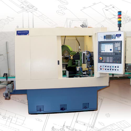
The RPB great flexibility allows to machine a wide range of engine valves with different length, head diameter, stem diameter and seat angles. The setup time is very fast. The grinding wheel has a Ø 610 mm.
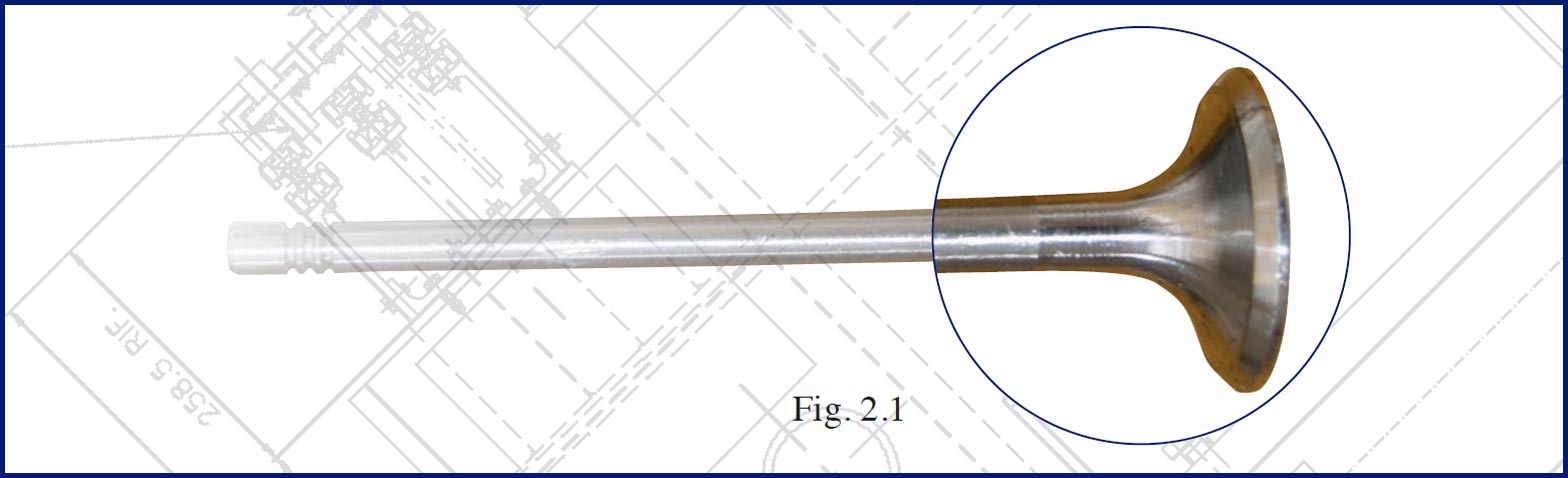
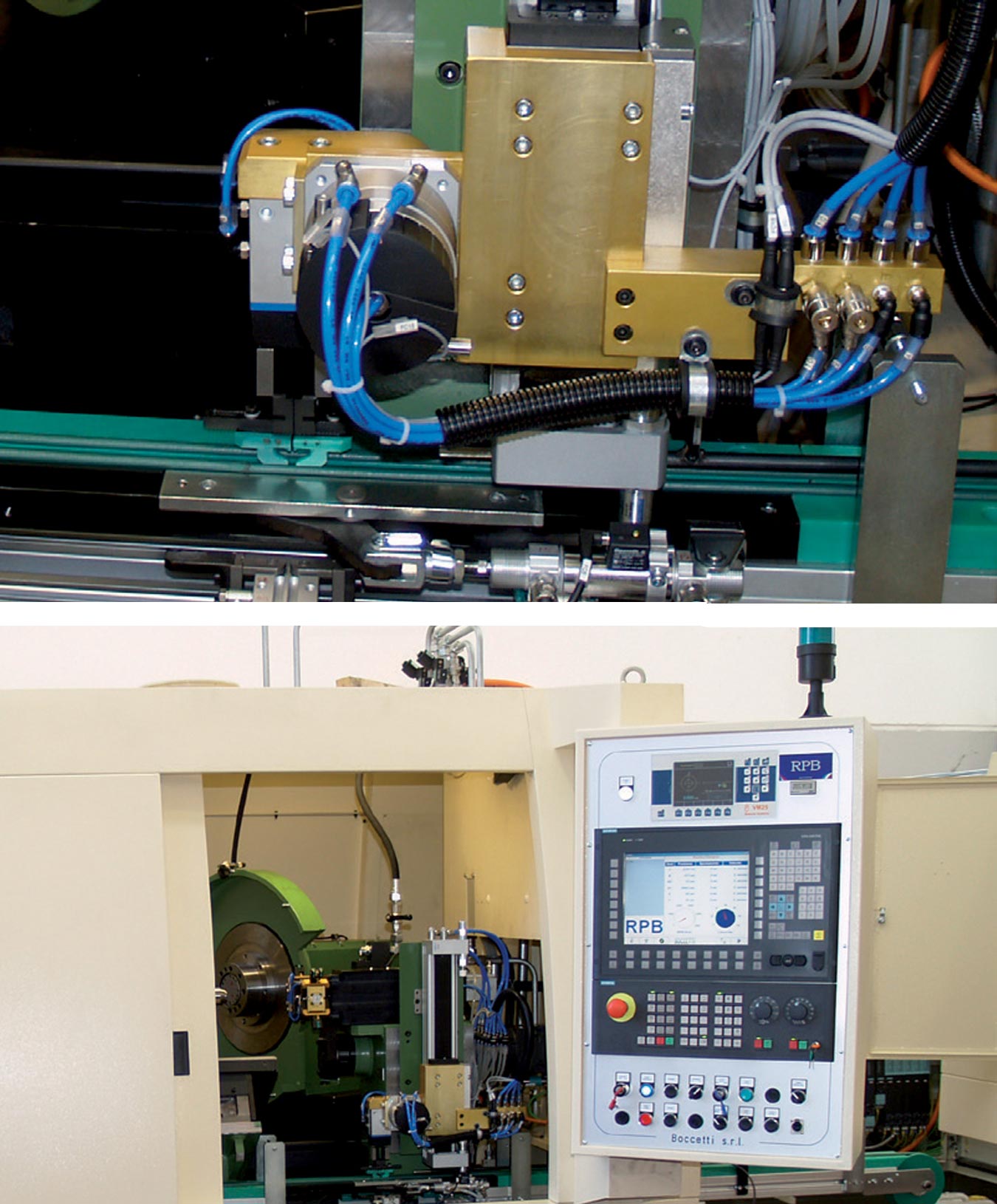
After loading the valve is held by a rotating collet of the workpiece spindle. This unit moves on the loading and unloading slide (T axis).
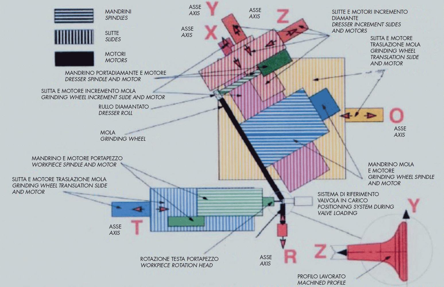
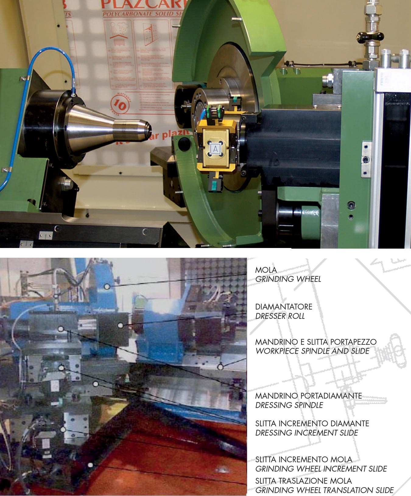
The grinding wheel and dressing assembly are mounted on the grinding wheel translation slide which allows, by a small movement parallel to the piece , to adjust and optimize the position “grinding wheel/valve.
LThe grinding wheel is put in rotation by an electric spindle mounted on a carriage running on the grinding wheel increment slide. The grinding wheel slide axis is at 60° compared to the valve axis. The grinding wheel dressing is obtained by a diamond roller assembled on two slides with orthogonal and independent motions in order to create the requested profile. The dresser crossed slides assembly is mounted on the grinding wheel increment slide.
The loader picks up the valve coming from a rubber string conveyor, it lifts that to the level of the workpiece head. Here the valve is clamped by the collet of a rotating shuttle to align it with the workpiece head axis. During the unloading the valve is clamped by the open collet, remained standby, and placed on the outlet rubber string conveyor.
The valve head, during the grinding operation, is pushed against the grinding wheel by two hard metal plates to counteract the grinding wheel thrust. This device is called Head Reaction Group.
The grinding wheel unit is assembled on the increment slide which grants the approaching motion to the valve and the increment motion to grind.
On the same slide are also mounted the dressing increment slides and the dressing spindle.
| TECHNICAL FEATURES | ||
|---|---|---|
| . | unit of measure | value |
| Valve size: head diameter stem diameter length |
mm. | 20 - 60 4,5 - 12 70 - 200 |
| Cycle time | pz/h | 400 |
| Grinding wheel sizes | mm. | 610 x 44 x 203,4 |
| Grinding wheel max speed. | mt./sec. | 100 |
| Grinding wheel spindle power | kW | 30 |
| Power supply | V/Hz | 400V 50Hz 3pH |
| Air supply | bar | 5 - 6 |
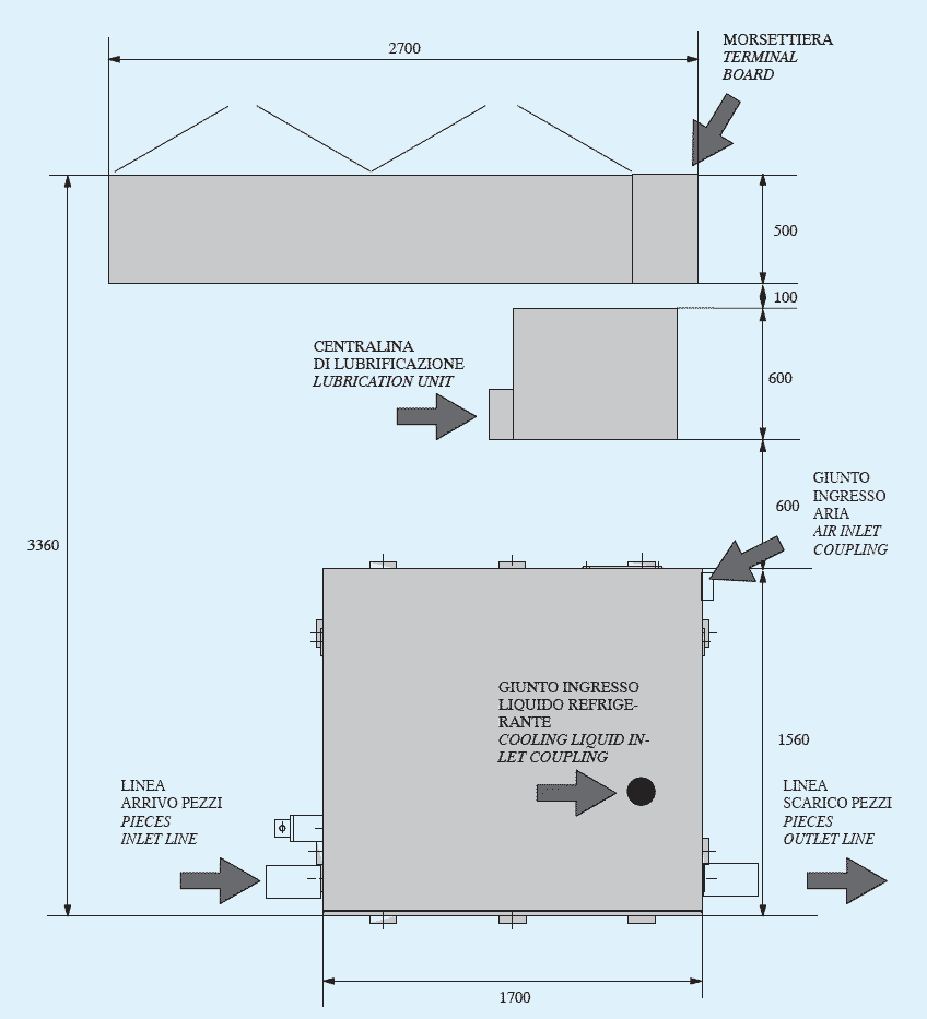
| Floor space (x height 2100 mm.) | mm. | 2200 x 1860 |
| Machine weight | kg. | 6500 |

.png)


